
 English
 中文简体
中文简体 русский
 日本語
日本語 Français
 Español
 عربى
عربىen
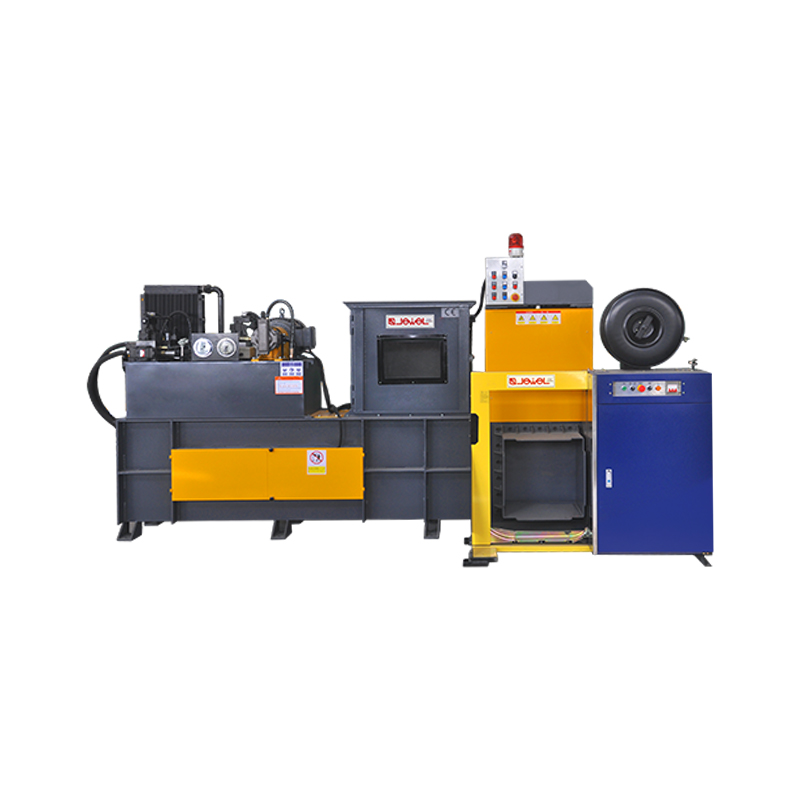
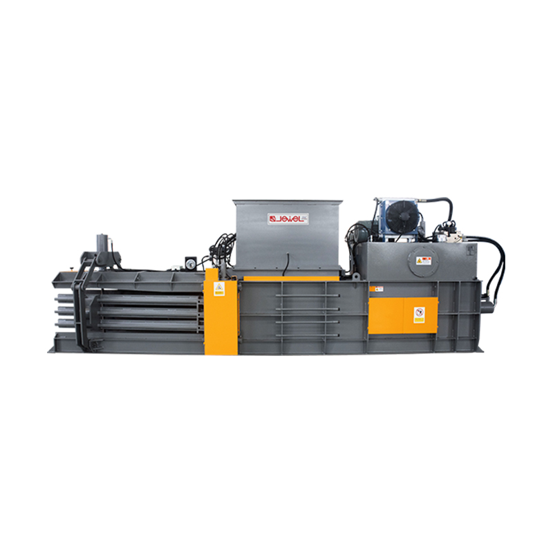
In the field of industrial waste recycling and renewable resource utilization, the application of metal balers plays a crucial role in improving operational eff...
READ MORE2026-07-31
Content
A properly engineered baler machine does more than compress waste — it changes how a facility manages space, labor, and outbound logistics. Whether the application involves cardboard, plastic film, textiles, or metal containers, the right bale machine reduces handling time on every shift and turns loose material into a manageable, uniform output. Facility managers who evaluate compaction equipment for the first time often focus only on chamber size, but daily throughput, tying method, and duty cycle rating matter just as much once the unit is running under real production conditions.
Material recovery operations, packaging-heavy warehouses, and container return points all share a common challenge: loose material accumulates faster than it can be moved out through normal channels. Without compaction, staff spend a disproportionate amount of time simply relocating waste rather than managing it. A well-matched baler machine addresses this at the source, converting scattered material into a form that is easier to count, store, and transport in a single motion.
Facilities that switch from manual compaction or open-top containers to a dedicated baler machine typically see the benefit within the first week of operation. Loose material that once required frequent pickups or excessive floor space is instead formed into dense, stackable blocks. The advantages below apply across most baler machine categories, from compact vertical units to larger continuous-feed systems, and they tend to compound over time as staff adjust their workflow around the equipment rather than around the material itself.
Compressed bales occupy a fraction of the volume of loose material, freeing up storage and staging areas that would otherwise be consumed by uncompacted waste. Many facilities reclaim entire sections of floor space once loose material stops piling up between pickups.
Fewer pickups are needed once material is baled, reducing the number of times staff or transport vehicles need to interact with the waste stream. This also lowers the wear on handling equipment used to move material around the site.
Loose cardboard, film, and containers scattered across a floor create tripping hazards and clutter. A bale machine keeps the area organized and consistent, which also makes routine safety inspections easier to pass without last-minute cleanup.
Hydraulic pressure is applied evenly across the compression chamber, producing bales of similar weight and dimension for predictable stacking and transport, which simplifies planning for outbound trailer loads.
Manual compaction by hand or foot places repetitive strain on staff over a full shift. Hydraulic compression removes this physical burden while producing a denser, more consistent result than manual methods can achieve.
Once a baler machine is calibrated for a given material type, cycle duration stays consistent from one load to the next, allowing supervisors to plan staffing and pickup schedules with more confidence.
Every bale machine, regardless of size or orientation, relies on a small set of core systems working together. Understanding these components helps facility managers evaluate build quality before committing to a unit, since two machines with similar external dimensions can perform very differently depending on how their internal systems are engineered.
The hydraulic cylinder is typically the single most expensive component in a bale machine, and its bore diameter directly determines the maximum compression force available. A larger bore allows the unit to reach higher pressure at the same pump output, which matters when processing denser materials such as compacted metal containers. Cylinder rods are usually chrome-plated to resist pitting and corrosion, since even small surface defects can damage internal seals over repeated cycles and lead to fluid leakage.
The compression chamber itself is built from thicker steel plate along the areas that absorb the most repeated stress, particularly around the press plate path and the door seams. Reinforcement in these zones prevents the chamber walls from bowing outward over years of continuous cycling, which would otherwise allow material to escape the sides during compression and reduce bale density.
| Component | Function | Typical Material |
| Hydraulic Cylinder | Generates the compression force applied to the loaded material | Chrome-plated steel rod |
| Compression Chamber | Contains the material during pressing and defines bale dimensions | Reinforced steel plate |
| Control Panel | Regulates cycle timing, pressure limits, and safety interlocks | Sealed electrical enclosure |
| Tying System | Secures the finished bale with wire or strap before ejection | Manual or automatic feed |
| Base Frame | Supports structural load and anchors the unit to the floor | Welded structural steel |
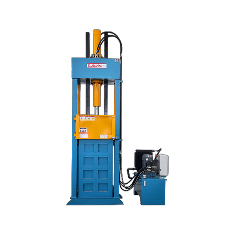
Orientation is one of the first decisions a facility needs to make. A vertical baler machine compresses material from top to bottom inside a narrow footprint, making it a common choice for locations with limited floor area, such as back-of-store rooms, small workshops, or single-shift processing points. Horizontal configurations, by contrast, allow continuous loading from the side and are typically selected for higher-volume operations that generate a steady stream of material throughout the day.
The loading pattern of a vertical baler machine means an operator generally finishes one full compression cycle before adding the next batch of material, since the chamber door sits directly above the press plate travel path. This sequential rhythm works well when material accumulates gradually over the course of a shift rather than arriving in a continuous stream. Because the footprint is narrow, these units can often be positioned against a wall or in a corner without disrupting existing workflow around them.
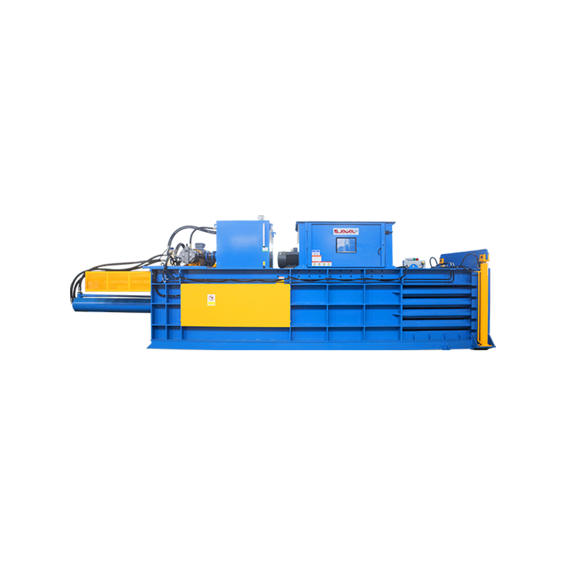
This continuous-feed capability is what allows horizontal configurations to reach significantly higher daily throughput, though it comes with a larger physical footprint and, in most cases, a dedicated concrete pad to support the added structural weight.
Material type has a direct effect on chamber pressure, cycle time, and tying strength. A cardboard baler machine is tuned for lightweight, high-volume fiber material, while a can baler machine is built to withstand the rigidity of aluminum and tin containers. The table below outlines how these two configurations typically differ in practice.
| Parameter | cardboard baler machine | can baler machine |
| Primary Material | Corrugated cardboard, paper | Aluminum cans, tin containers |
| Compression Ratio | Approximately 8:1 to 10:1 | Approximately 3:1 to 5:1 |
| Chamber Pressure Demand | Moderate | High |
| Tying Requirement | Standard wire or strap | High-tensile wire |
| Bale Density | Lower relative weight | Higher relative weight |
Cardboard presents a unique compaction challenge because of its internal air pockets. Corrugated fiber has a fluted inner layer that traps significant volume relative to its weight, which is why a cardboard baler machine can typically reach compression ratios well above what is possible with denser materials. The trade-off is that cardboard requires a longer hold time within the chamber to allow trapped air to escape fully, since releasing pressure too early can cause partially compressed bales to expand once the tying wire is engaged.
Metal containers behave in the opposite way. Aluminum and tin have far less internal air space, so a can baler machine reaches its target density more quickly per cycle but requires substantially more force to achieve meaningful volume reduction. This is why chamber pressure ratings for can-focused units tend to sit at the higher end of the available range, and why tying wire on these units is typically rated for greater tensile load than the wire used on fiber-focused equipment.
Not every facility deals exclusively in cardboard or metal. Stretch film, shrink wrap, and lightweight plastic packaging present their own compaction challenges, since these materials tend to be slippery and resist forming a stable bale shape on their own. A bale machine handling film typically runs a longer compression hold and relies on tighter tying spacing to keep the finished block from unwinding during transport.
Mixed material streams, where fiber, film, and occasional rigid plastic arrive together, require a baler machine with a wider operating pressure range rather than a unit tuned narrowly for a single material. Facilities processing mixed input generally benefit from a mid-range chamber size that avoids the extremes of either lightweight fiber-only equipment or high-pressure metal-focused units, since flexibility in daily operation often matters more than maximum output for any single material type.
Requires extended hold time and tighter wire spacing to prevent the bale from loosening after the chamber door opens.
Compacts unevenly if fed in large uncut sheets, so pre-shredding or folding before loading improves bale consistency.
Behaves closer to fiber material under pressure but benefits from slightly longer cycle duration to settle fully.
Compresses well but tends to expand faster than other materials once released, making tying tension especially important.
The internal process of a baler machine follows a consistent sequence regardless of orientation or material type. Understanding each stage clarifies why cycle timing, chamber size, and tying method matter when comparing available configurations.
Loose material is fed into the compression chamber either manually or through a conveyor feed, depending on the scale of the operation. Even distribution across the chamber floor at this stage helps avoid uneven density once compression begins, since material stacked unevenly on one side can cause the press plate to meet resistance at an angle.
The hydraulic cylinder drives the press plate forward, applying steady pressure until the material reaches the target density. Pressure builds progressively rather than in a single motion, which reduces mechanical shock on the cylinder and allows air trapped within the material to escape gradually rather than resisting the plate all at once.
Pressure is held briefly to allow the compressed block to settle into a stable, uniform shape before tying begins. This dwell period is especially important for fiber-based material, where trapped air needs time to fully release before the bale is secured.
Wire or strap is fed through pre-set channels and tightened around the bale to keep it intact through transport and storage. Channel spacing is fixed during manufacturing to match the expected bale dimensions, ensuring each tie sits at a consistent interval along the length of the block.
The chamber door releases and the finished bale is pushed or lowered out of the unit, clearing the chamber for the next cycle. On units with automatic ejection, this stage is timed to coincide with the return stroke of the press plate, minimizing idle time between cycles.
The press plate retracts fully and the control system confirms the chamber is clear before allowing the next loading stage to begin, preventing accidental double-compression of a partially ejected bale.
Not every location has the same material volume or floor plan, so baler machine selection should start with an honest assessment of daily output rather than raw compression tonnage. The scenarios below reflect common patterns seen across different facility types.
Daily cardboard volume is moderate and space is limited, making a compact vertical baler machine the practical choice for keeping stockrooms clear.
Continuous inbound and outbound packaging generates steady cardboard waste, favoring a horizontal cardboard baler machine with higher throughput.
Locations collecting aluminum and tin containers need the higher chamber pressure and reinforced tying of a can baler machine to form stable, transport-ready bales.
Mixed material streams including film, fiber, and textile scraps benefit from a mid-size bale machine capable of handling variable input without frequent reconfiguration.
The service life of a baler machine depends heavily on frame construction and the quality of the hydraulic circuit. Compression chambers built from reinforced steel plate resist deformation under repeated cycles, while a properly sized hydraulic pump avoids the overheating that shortens seal life. Pressure relief valves and flow control components regulate how quickly the press plate advances, which affects both cycle speed and mechanical wear over time.
Base frames are typically welded rather than bolted at load-bearing points, since bolted joints under constant vibration tend to loosen faster than welded seams. A stable base also keeps the compression chamber aligned, which prevents uneven bale shapes that can loosen during transport. Facilities running multiple shifts should pay particular attention to duty cycle ratings, since a unit designed for intermittent use will wear noticeably faster under continuous operation.
Motor sizing is another factor that influences reliability, since an undersized motor working near its maximum rated output for extended periods runs hotter and wears faster than a motor with reasonable headroom above the typical operating load. Facilities planning for future volume growth often choose a baler machine with slightly more motor capacity than current daily needs require, avoiding the cost of a full equipment upgrade a few years into operation.
Compression equipment carries inherent risk, so control systems are designed around multiple layers of protection. Dual-hand start controls require both hands to remain on the control panel before a compression cycle begins, keeping hands clear of the chamber opening. Interlocked access doors prevent the hydraulic cylinder from engaging unless the chamber is fully sealed, and pressure sensors halt the cycle automatically if resistance exceeds the safe operating threshold.
For vertical baler machine units, an additional door interlock is common at the top-loading point, since the opening sits closer to operator reach during loading. Emergency stop controls are positioned at accessible points around the frame so that any operator nearby can halt the cycle immediately if needed.
Beyond the interlocks themselves, control panels typically log fault conditions so that maintenance staff can review what triggered a stoppage rather than guessing at the cause. This diagnostic layer shortens troubleshooting time considerably, since a logged pressure fault points directly to the hydraulic circuit while a logged door-sensor fault points to the mechanical interlock, allowing staff to check the correct system first instead of inspecting the entire unit.
Guarding around moving components, including the press plate travel path and any exposed drive linkages, is fixed in place with fasteners that require tools to remove, discouraging casual bypass during normal operation. Warning labels near the loading point reinforce the interlock behavior visually, reminding operators of correct loading posture even during repetitive, high-volume shifts when attention naturally drifts.
Routine maintenance for a baler machine centers on three areas: hydraulic fluid condition, seal integrity, and tying mechanism calibration. Hydraulic fluid should be inspected for contamination on a regular schedule, since particulate buildup accelerates wear on internal cylinder surfaces. Seals around the compression chamber should be checked for cracking or leakage, particularly in units running multiple cycles per hour.
Tying systems, whether manual or automatic, require periodic tension checks to confirm that finished bales stay intact during handling. Loose tension is one of the most common causes of bale failure during transport, and it is also one of the easiest issues to catch during a routine inspection. Facilities that follow a consistent maintenance schedule typically extend the operational life of their bale machine well beyond units that receive only reactive repairs.
Filter replacement on the hydraulic circuit deserves particular attention, since a clogged filter restricts fluid flow and forces the pump to work harder to maintain target pressure. Over time this added strain shows up as slower cycle times before it eventually leads to more serious pump wear. Scheduling filter changes based on operating hours rather than calendar time gives a more accurate maintenance interval for facilities running variable shift patterns.
Lubrication points along guide rails and hinge mechanisms should also be checked during routine service, since dry metal-on-metal contact at these points increases friction and can eventually cause the press plate to travel unevenly within the chamber. A short lubrication routine performed weekly is generally enough to prevent this issue from developing into a larger mechanical problem.
Beyond equipment specifications, the way a facility schedules its baler machine use has a real effect on efficiency. Running compression cycles in small, frequent batches throughout the day keeps material from accumulating into an unmanageable pile, while consolidating everything into a single end-of-shift session can leave overflow material sitting on the floor in the meantime. Facilities with predictable material flow generally benefit from setting fixed compression intervals rather than reacting only when the collection area starts to fill.
Staffing assignments around the equipment also matter. Designating a single trained operator per shift for loading and tying tasks tends to produce more consistent bale quality than rotating the responsibility among multiple staff members with varying levels of familiarity with the controls. Consistency in operation translates directly into consistency in output, which in turn makes outbound transport planning more predictable from one week to the next.
Tying method has a direct impact on daily throughput. Manual tying requires an operator to thread and secure wire after each compression cycle, which works well for lower-volume vertical baler machine setups where cycle frequency is limited. Automatic tying systems feed and tension wire without operator intervention, which becomes valuable on higher-volume cardboard baler machine or can baler machine configurations where cycle frequency would otherwise create a bottleneck at the tying stage.
| Tying Method | Operator Involvement | Best Suited For |
| Manual Tying | Required at every cycle | Lower-volume vertical baler machine use |
| Semi-Automatic Tying | Partial, operator confirms cycle | Mid-volume mixed material streams |
| Automatic Tying | Minimal, system self-feeds wire | High-volume horizontal configurations |
Selecting the correct combination of orientation, chamber pressure, and tying method allows a baler machine to match the actual material flow of a facility rather than being oversized or undersized for daily conditions. A unit sized correctly from the start avoids the excess energy use of an oversized press and the constant cycling strain of an undersized one, keeping both operating cost and downtime under control over the equipment's working life.
Chamber dimensions determine both the size of the finished bale and how many loading cycles are needed to process a given volume of material. A smaller chamber requires more frequent cycles to keep pace with the same daily input, which increases wear on the tying mechanism and the hydraulic system over time compared to a larger chamber processing the same total volume in fewer cycles. At the same time, an oversized chamber running well below capacity wastes floor space and can produce inconsistent bale density if loads are too small to fill the chamber evenly.
A practical approach is to estimate average daily material weight first, then work backward to a chamber size that keeps the unit running at a moderate, sustainable cycle count rather than either sitting idle for long stretches or running near-continuous cycles that leave little margin for maintenance downtime. This balance is different for every facility, which is why chamber size should be selected based on measured material flow rather than general assumptions about facility type alone. Facilities that take the time to map their material volume, available floor space, and staffing pattern before selecting a configuration tend to get years of stable service from equipment that might otherwise have been replaced early due to a poor initial match between machine and material.
Recommended products
In the field of industrial waste recycling and renewable resource utilization, the application of metal balers plays a crucial role in improving operational eff...
READ MOREMetal Recycling Equipment Guide How Does a hydraulic metal baler Actually Compress Scrap Metal Into Dense Blocks? A hydraulic metal baler machine converts loos...
READ MOREIn the modern industrial waste management and renewable resource circulation system, the efficient disposal of waste plastics has become a core link for enterpr...
READ MOREThe Short Answer First A production manager in a corrugated packaging plant recently showed me two photographs. The first was a wall of baled cardboard and pla...
READ MOREIn the context of the global circular economy and efficient industrial waste utilization, metal resource recycling demands higher equipment performance. Whether...
READ MOREOn modern ocean-going vessels, luxury cruise ships, and offshore platforms, solid waste management has always been a severe challenge. Due to the extremely limi...
READ MORE
Waste Types
Categories
 Custom Baling Press Machine Manufacturers