English
 中文简体
中文简体 русский
 日本語
日本語 Français
 Español
 عربى
عربى01
More Consistent Bale Density
Pressure loss, internal hydraulic leakage, worn chamber liners and incorrect holding time can produce loose or uneven bales. Regular inspection helps maintain repeatable compression results.
2026-07-10
Content
Horizontal Baling Equipment Maintenance Guide
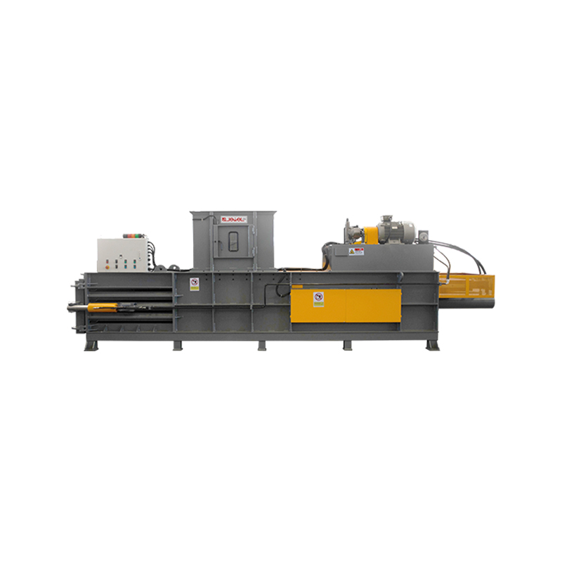
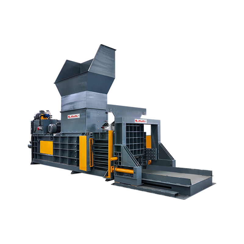
Routine maintenance directly affects bale density, operating stability, hydraulic efficiency and unplanned downtime. For facilities processing waste paper, cardboard, plastic film, textile scraps and other compressible materials, a structured maintenance program helps automatic horizontal balers maintain consistent performance under continuous production conditions.
This guide explains daily inspection procedures, hydraulic system care, automatic tying maintenance, fault diagnosis and component replacement planning. It also helps operators identify the difference between minor adjustments and problems that require professional service.
Maintain clean oil, effective filtration and controlled operating temperature.
Inspect wire paths, guide components, cutters and tension settings.
Prevent conveyor misalignment, chamber blockage and uneven loading.
Effective fully automatic horizontal balers maintenance should combine every-shift cleaning, weekly mechanical inspection, scheduled hydraulic service, tying-system adjustment and accurate operating records. Maintenance intervals should be shortened when the machine handles dusty, abrasive, wet or highly elastic materials.
Maintenance Value
Pressure loss, internal hydraulic leakage, worn chamber liners and incorrect holding time can produce loose or uneven bales. Regular inspection helps maintain repeatable compression results.
Clean wire channels, correctly adjusted tension and sharp cutting components reduce incomplete ties, broken wire and repeated machine stops.
Lubricated guide surfaces, correctly tensioned conveyors and clean hydraulic oil reduce unnecessary wear on cylinders, pumps, rollers and sliding components.
Small abnormalities can be corrected before they develop into pump damage, cylinder seal failure, conveyor breakdown or control-system faults.
Service Schedule
| Maintenance Interval | Inspection Area | Required Work | Problem Prevented |
| Before Every Shift | Hydraulic station | Check oil level, visible leakage, hose condition and abnormal pump noise. | Pressure instability, pump cavitation and oil loss. |
| Every Shift | Compression chamber | Remove loose material around the platen track, sensors and discharge area. | Platen obstruction, false sensor signals and uneven bale formation. |
| Every Shift | Tying mechanism | Inspect wire supply, feeding path, cutter area and completed tie quality. | Wire breakage, incomplete cutting and loose bales. |
| Weekly | Conveyor system | Check belt tracking, tension, roller rotation and material accumulation. | Belt edge damage, slipping and interrupted feeding. |
| Weekly | Mechanical structure | Inspect bolts, guide rails, wear plates, brackets and moving joints. | Excessive vibration, misalignment and structural looseness. |
| Monthly | Electrical controls | Clean the control cabinet filter, check terminals and verify sensor mounting. | Overheating, unstable signals and unexpected control faults. |
| Scheduled Service | Hydraulic oil and filters | Test oil condition, inspect filter indicators and replace components as required. | Valve contamination, reduced flow and hydraulic pump wear. |
| Annual Inspection | Complete machine | Inspect cylinders, pump performance, motor insulation, frame condition and safety devices. | Major mechanical, electrical and hydraulic failure. |
Maintenance frequency should be based on operating hours, material characteristics, ambient temperature and production intensity. The machine manual and actual operating records should take priority over general reference intervals.
Hydraulic Care
The hydraulic system supplies the force required for feeding, compression, holding and bale discharge. A stable hydraulic circuit is essential for maintaining bale density and cycle consistency. Fully automatic horizontal balers maintenance should focus on oil cleanliness, temperature control, pressure stability and leakage prevention.
Excessive oil temperature reduces viscosity, accelerates oil oxidation and shortens seal life. Persistent overheating may be caused by a blocked cooler, unsuitable oil viscosity, internal valve leakage, continuous overload or hydraulic pump wear.
Dust, water and metal particles can damage precision valves and pump surfaces. Oil should be added through a clean filtration device. The tank cover, breather and filling area should be cleaned before service work begins.
Check hoses for cracking, abrasion, swelling and loose fittings. Small leaks should not be ignored because they can introduce air into the circuit, lower system pressure and contaminate the working area.
Automatic Tying
Remove dust and fragments from guide tubes, wire channels and feeding wheels. Resistance inside the wire path can prevent the wire from reaching the correct position.
Insufficient feeding-wheel pressure can cause slipping. Excessive pressure may deform the wire or accelerate wheel wear.
Excessive tension increases wire breakage risk. Insufficient tension allows the compressed material to expand after discharge.
A worn cutter may leave rough ends or fail to separate the wire completely. Check blade condition and cutting clearance.
Fault Diagnosis
| Observed Problem | Possible Cause | Recommended Check |
| Bale density is lower than expected | Low hydraulic pressure, short holding time, wet material or internal leakage. | Verify pressure settings, oil temperature, cylinder sealing and material moisture. |
| The main platen moves slowly | Blocked filter, insufficient oil, pump wear or excessive system temperature. | Check oil level, filter condition, pump noise and cooler cleanliness. |
| Wire repeatedly breaks | Excessive tension, damaged guide surface or unsuitable wire specification. | Reduce tension gradually and inspect every contact point along the wire path. |
| Wire cannot feed into position | Blocked guide tube, worn feeding wheel, sensor misalignment or drive fault. | Clean the channel, inspect wheel pressure and confirm sensor signals. |
| Conveyor belt moves to one side | Uneven tension, material accumulation, roller misalignment or bearing wear. | Clean the conveyor, inspect rollers and adjust both sides evenly. |
| Hydraulic pump produces sharp noise | Air entering the system, low oil level, blocked suction filter or cavitation. | Stop the machine and inspect the suction circuit before continued operation. |
| Machine stops during an automatic cycle | Sensor contamination, safety interlock activation, overload or control fault. | Read the control message, clean sensors and verify all safety devices. |
Material-Specific Care
Paper dust can accumulate around sensors, electrical cabinet filters, wire channels and hydraulic coolers. Cleaning frequency should increase when handling dry corrugated material continuously.
Film can wrap around rollers, shafts and conveyor components. Its high recovery force may also require careful adjustment of holding time and tying tension.
Fibers may collect around moving joints and rotating components. Long strips can interfere with feeding equipment or enter guide mechanisms.
Mixed waste may contain hard objects that damage the chamber, cutting components or conveyor. Material inspection before feeding becomes especially important.
Spare Parts Planning
Maintenance Records
Maintenance records should include operating hours, hydraulic oil temperature, pressure behavior, bale weight, cycle time, wire consumption and repeated fault messages. Small changes in these values often reveal component deterioration before a complete failure occurs.
May indicate reduced hydraulic flow, pump wear or movement resistance.
May indicate lower pressure, reduced chamber filling or unsuitable parameter settings.
May indicate cooler blockage, internal leakage or continuous overload.
May indicate incorrect bale length, repeated tying attempts or unstable wire feeding.
Safe Maintenance Procedure
Stop material feeding and allow the current cycle to finish where possible.
Switch off the main power supply and apply an approved lockout procedure.
Release stored hydraulic pressure before disconnecting hoses or valves.
Secure moving components before entering the chamber or discharge area.
Do not bypass safety switches, guards, emergency stops or access-door interlocks.
Return all guards to their correct position before test operation begins.
Equipment Selection
Maintenance requirements are influenced by the original machine configuration. Buyers evaluating automatic horizontal balers should review not only pressing force and production capacity, but also component accessibility, control functions, hydraulic cooling and after-sales parts support.
Clearly arranged pumps, valves, filters and inspection points make routine service faster and reduce the risk of contamination during maintenance.
Replaceable chamber liners and guide components can reduce structural repair work after long-term operation with abrasive materials.
A control system with readable operating messages helps technicians locate sensor, overload and cycle-sequence problems more efficiently.
Correctly sized cooling equipment supports stable operation in warm environments and during long production shifts.
Conveyor, hopper and feeding-opening dimensions should match the material size and required throughput to prevent repeated overload.
Hydraulic diagrams, electrical drawings, maintenance schedules and spare-parts lists make long-term equipment management more efficient.
Maintenance Questions
Replacement should be based on oil condition, operating hours, temperature history and contamination level. Oil analysis is more reliable than replacing oil according to calendar time alone.
Common causes include insufficient holding time, low compression pressure, high material elasticity, loose tying tension or an unsuitable number of ties.
Continuous operation is not recommended when oil temperature remains above the permitted range. The cooler, oil level, filtration, pump condition and system load should be checked.
Bale expansion, incorrect wire tension, chamber contamination or misalignment under load may affect the tying path. Inspection should be performed with attention to actual loaded conditions.
Provide the machine model, processed material, operating hours, fault message, hydraulic pressure, oil temperature and clear photographs or videos of the affected area.
Factory Engineering Support
Material type, feeding method, bale size, desired capacity, available installation space and local power conditions all influence equipment configuration. A factory-based evaluation can help define the appropriate pressing force, conveyor arrangement, tying system, cooling capacity and maintenance access before production.
Recommended products
A properly engineered baler machine does more than compress waste — it changes how a facility manages space, labor, and outbound logistics. Whether the applic...
READ MOREINDUSTRY GUIDE Waste Compression and Material Handling What Is a Horizontal Baler and Which Type Fits Your Material? Horizontal balers compress large volumes...
READ MOREIn modern large-scale production and logistics warehouse management, the efficiency of the packaging process often determines the flow speed of the entire suppl...
READ MOREEfficient Resource Recovery: The Core Role of a plastic baling machine in Modern Waste Management In the era of the circular economy, the efficient processing ...
READ MOREIn modern industrial waste management, volume reduction and density enhancement are key to efficient transport and resource circulation. As industrial productio...
READ MOREIn industrial manufacturing, material recycling, and urban waste management systems, solid waste volume reduction and resource utilization are core links to red...
READ MORE
Waste Types
Categories
 Custom Baling Press Machine Manufacturers